Connecting Accessories
Do not use the device to control or power a winch. Failure to follow this notice could cause damage to your vehicle or your device.
Accessory requirements:
-
Verify the amperage rating of each accessory before wiring it to the Garmin PowerSwitch™ device. The device supports accessories up to 30 A for each channel and a maximum of 100 A for the entire system.
-
Use 10 AWG (6 mm2) wires for accessories that use 20 to 30 A.
-
Use 12 AWG (4 mm2) wires for accessories that use 10 to 20 A.
-
Use 14 AWG (2.5 mm2) wires for accessories that use less than 10 A.
-
Use the appropriate size terminals for all accessory connections.
-
Crimp all terminal connectors securely.
-
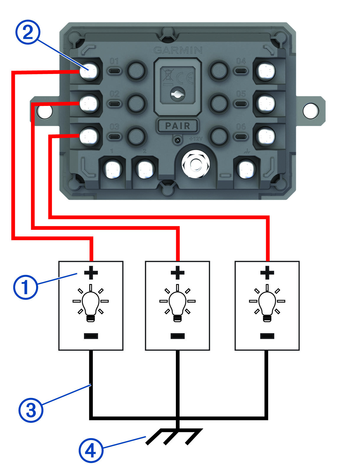
Connect the positive wire from the accessory
 to one of the accessory terminals
  on the
Garmin PowerSwitch device.
on the
Garmin PowerSwitch device.
-
Connect the negative or ground wire
 to an unpainted ground stud
  on the vehicle frame, to a ground distribution block, or directly to the negative terminal on the battery.
Do not connect the accessory ground wires to the ground terminal (GND) on the Garmin PowerSwitch device. Failure to heed this notice could result in personal or property damage, or negatively impact device functionality.