Installing the Transducer on the Perspective Mode Mount
Labels identifying the parts bags required for this procedure:


You must secure the transducer cable to the shaft or other secure location during installation. Damage to the transducer cable wire or the cable jacket can cause transducer failure.
NOTE:
To avoid obstructions in the sonar image, you should mount the transducer on the shaft as far from the motor as possible.
-
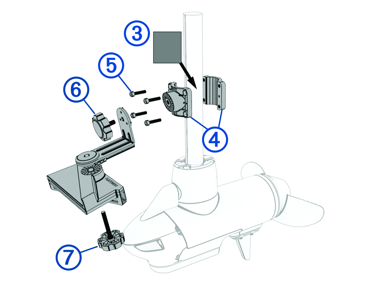
Remove the perspective mode extension arm, the front half of the mounting bracket, and the short knob from parts bag
 .
.
-
Remove the back half of the mounting bracket and four screws from parts bag
 .
NOTE: For a shaft diameter greater than 42 mm (1.65 in.), use the four screws from parts bag
.
NOTE: For a shaft diameter greater than 42 mm (1.65 in.), use the four screws from parts bag instead.
-
Remove the long knob from parts bag
 .
.
-
If the trolling motor shaft is equal to or less than 25 mm (1 in.) in diameter, remove the rubber liner from parts bag .
-
Identify the arrow
 on the front half of the mounting bracket to ensure that you orient the bracket with the wide end of the slant
  at the top when you attach the bracket to the trolling motor shaft.
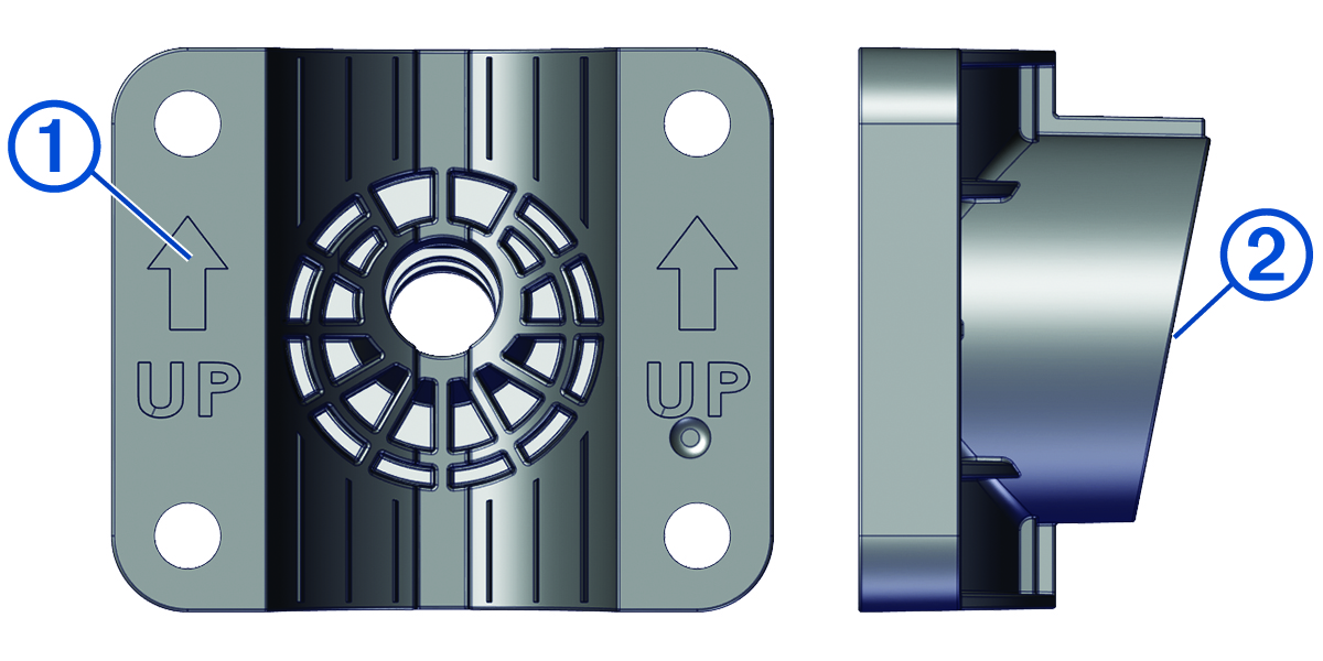
NOTE: The perspective mode bracket has an 11-degree angle to allow the extension arm to transition between all three sonar views. -
If you are installing the transducer on a trolling motor shaft equal to or less than 25 mm (1 in.) in diameter, wrap the rubber liner
 around the shaft in the location you want to install the mount.
NOTE: The rubber liner is not needed when installing the transducer on a trolling motor with a shaft diameter larger than 25 mm (1 in.). -
Orient the mounting bracket
 on the shaft so the arrows on the inside of the front half of the bracket point up.
The bracket should be aligned so the center screw hole faces the front of the trolling motor.
-
Place bracket around the rubber liner on the trolling motor shaft, insert the screws
 into the mount bracket, and secure them using the 5 mm hex wrench in parts bag .
-
With the 90-degree angle pointing downward, attach the shorter length of the extension arm to the mounting bracket using the shorter knob
 .
.
-
Place the transducer below the longer length of the extension arm and attach it using the longer knob
 .
NOTE: You can secure the extension arm to the mounting bracket and the transducer to the extension arm using the included low-profile hardware instead of the knobs if you do not plan to switch transducer modes frequently during use (Installing the Transducer Using Low Profile Mounting Hardware).
.
NOTE: You can secure the extension arm to the mounting bracket and the transducer to the extension arm using the included low-profile hardware instead of the knobs if you do not plan to switch transducer modes frequently during use (Installing the Transducer Using Low Profile Mounting Hardware).