Installing the Transducer on the Perspective Mode Mount
You can use the perspective mode mount to install the transducer in the perspective or side shaft configuration.
Labels identifying the parts bags required for this procedure:


NOTE:
To avoid obstructions in the sonar image, you should mount the transducer on the
shaft as far from the motor as possible.
-
Remove the perspective mode
bracket from parts bag
 .
.
-
Remove the adapter disc from
parts bag
 , which is located within parts bag
  .
.
-
Remove the back half of the
mounting bracket and four screws from parts bag
 .
NOTE: For a shaft diameter greater than 42 mm (1.65 in.), use the four screws from parts bag
.
NOTE: For a shaft diameter greater than 42 mm (1.65 in.), use the four screws from parts bag instead.
-
Remove the knob from parts bag
 .
.
-
If the trolling motor shaft is
equal to or less than 25 mm (1 in.) in diameter, remove the rubber liner from
parts bag .
-
If you are installing the
transducer on a shaft equal to or less than 25 mm (1 in.) in diameter, wrap the
rubber liner
around the shaft at the location where you plan to install the bracket.
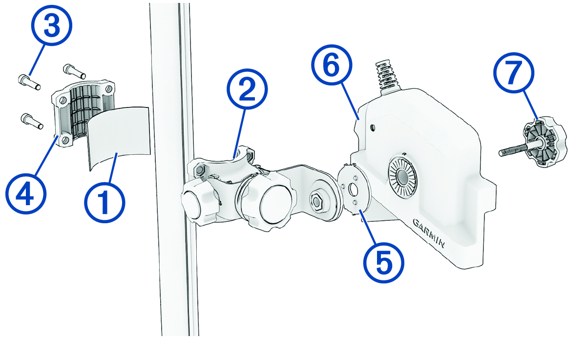
NOTE: The rubber liner is recommended for any shafts smaller than 38 mm (1.5 in.). The perspective mount does not support shafts smaller than 31 mm (1.25 in.). -
Insert the screws into the back of
the mounting bracket , and secure them to the front bracket using the 5 mm hex wrench
in parts bag .
-
Transition the trolling motor
from the deployed to the stowed position and back again to test the location of
the mounting bracket and make any adjustments as needed.
If you are mounting onto a Force® or Force Pro trolling motor, you must install the perspective mount in the proper location so that the transducer aligns with the latch gap. Failure to do so can result in damage to your transducer or trolling motor.
