Viewing Modes
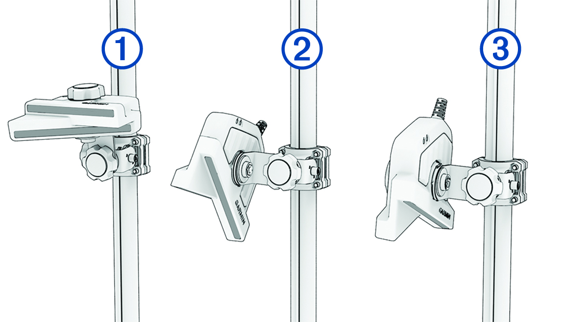
Using the perspective mode mount, you can change the orientation angle of the transducer between three sonar views.
When installing the transducer using the recommended adjustment knobs, no tools are necessary to change the orientation between these fields of view. You must loosen the knobs to change the orientation of the arm and transducer, and tighten them to set the orientation.
You can verify the sonar view using the notches on the perspective mount bracket and the transducer.

| Glyph | Disc Marking | Meaning |
|---|---|---|
|
F|D |
Starboard side forward or downward view |
|
|
P |
Perspective view |
|
|
F|D |
Port side forward or downward view |
|
|
D |
Port side downward view |
|
|
F |
Port side forward view |
|
|
P |
Perspective view |
|
|
F |
Starboard side forward view |
|
|
D |
Starboard side downward view |

|
|
Perspective view (notches and ) |
|---|---|
|
|
Forward view (notches and ) |
|
|
Downward view (notches and ) |
|
|
Perspective view (notches and ) |
|---|---|
|
|
Forward view (notches and ) |
|
|
Downward view (notches and ) |
You should align the marks on the transducer and bracket to verify the appropriate orientation before tightening the knob.