NMEA 2000 Network Connection
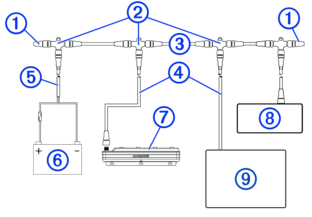
This diagram shows a sample installation which you can scale to apply to the NMEA 2000® network on your vessel. The device must receive power from a dedicated power connection and does not receive power from the NMEA 2000 network (Connecting to Power).
If you are unfamiliar with the needs of a NMEA 2000 network, you should read the “NMEA 2000 Network Fundamentals” chapter of the Technical Reference for NMEA 2000 Products. To download the reference, go to garmin.com/manuals/nmea_2000.
|
Item |
Description |
Notes |
|---|---|---|
|
|
NMEA 2000 terminator |
NMEA 2000 terminators must connect to each end of the NMEA 2000 backbone. |
|
|
NMEA 2000 T-connector |
NMEA 2000 T-connectors must connect to one another using the sides of each T, and they must connect to NMEA 2000 devices using drop cables connected to the top of each T. |
|
|
NMEA 2000 Backbone |
|
|
|
NMEA 2000 drop cable |
A NMEA 2000 drop cable connects a device to the NMEA 2000 network. A NMEA 2000 drop cable should not exceed 6 m (20 ft.). |
|
|
NMEA 2000 power cable |
|
|
|
12 V power source |
If you are using a Garmin Spectra™ LED control module with a 24 Vdc power source and LEDs, you must not connect the NMEA 2000 network to the 24 Vdc source. Connecting the NMEA 2000 network to a power source greater than 12 Vdc will damage connected devices. NOTE:
The
NMEA 2000 network and all LED control modules should connect to the same ground location.
|
|
|
Garmin Spectra LED control module |
The Garmin Spectra LED control module must connect to the NMEA 2000 network, to a power source, and to lighting devices to function correctly. |
|
|
Fusion® stereo (optional) |
The Fusion stereo must have a power connection separate from the NMEA 2000 network. |
|
|
Garmin® chartplotter |
The Garmin chartplotter must have a power connection separate from the NMEA 2000 network. |