Connection Considerations
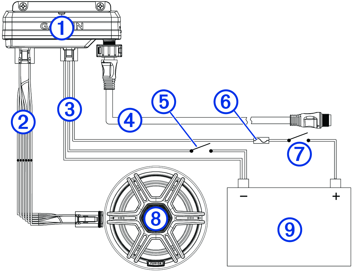
You should carefully plan the layout of the device, the power wiring, the NMEA 2000® network, and all LED lighting devices before making any connections. This is a connection overview. See the relevant connection sections for more information on particular connections.
|
|
Garmin Spectra™ LED Control Module |
|---|---|
|
|
LED wiring harness |
|
|
Power wiring harness |
|
|
NMEA 2000 cable |
|
|
Momentary switch (optional) |
|
|
Appropriately rated slow-blow fuse (not included) |
|
|
Ignition or ACC switch (recommended) |
|
|
12 or 24 Vdc LED lighting (LED speaker in this example) |
|
|
12 or 24 Vdc power source |
When making connections, observe these considerations.
-
This device supports a maximum of 2 A per LED wiring harness. When planning lighting connections, consider the power needs of all potential load combinations to ensure that the total active load does not exceed 2 A per LED wiring harness when in use.
-
You must connect all lighting to a common ground.
-
You must make all bare wire connections using appropriately sized marine-grade, waterproof connectors or waterproof heat-shrink.
-
You must insulate any unused bare wire connections after completing installation.
-
When extending wires, you must use the appropriate wire gauge for the individual wires on the wiring harnesses.
-
To avoid interference, avoid bundling or routing speaker and LED wires together.
-
This device must connect to the same NMEA 2000 network as the chartplotter or stereo you want to use for controlling the LED lighting (NMEA 2000 Network Connection).