-
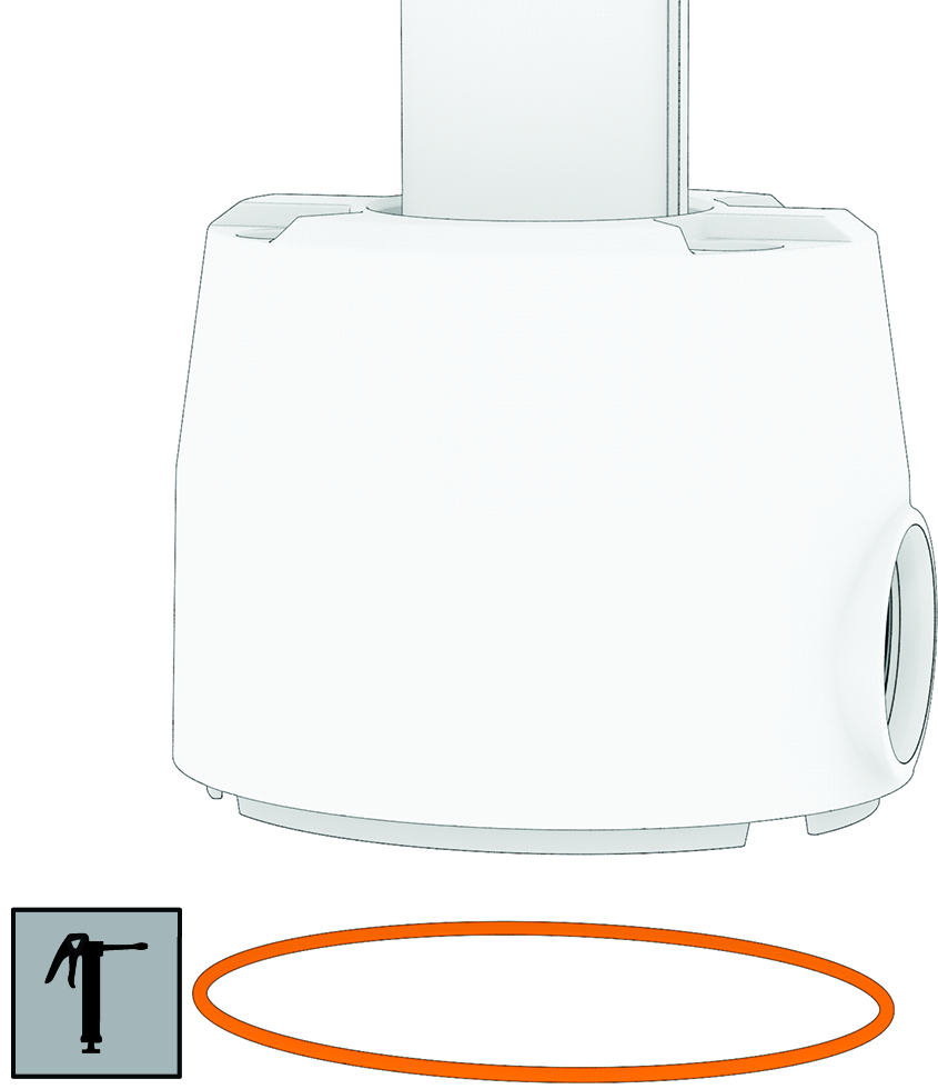
Remove the large 78 mm (3 in.) O-ring on the shaft base, and discard it.
-
Using the packet included in the shaft and motor hardware service kit, apply grease to the new 78 mm (3 in.) O-ring in the shaft and motor hardware service kit.
-
Place the new 78 mm (3 in.) O-ring in the groove on the shaft base.
-
Using canned compressed air or an air compressor, blow out any dirt or debris in the four threaded holes on the top of the propeller drive motor.
-
Apply a medium-strength thread-locking compound such as
LOCTITE® 243™ to the threads in the four threaded holes on the top of the propeller drive motor.
NOTICE
Thread-locking compound is required in these holes to maintain a tight connection between the shaft base and the propeller drive motor. Failure to use thread-locking compound can lead to water ingress and damage to the motor.
-
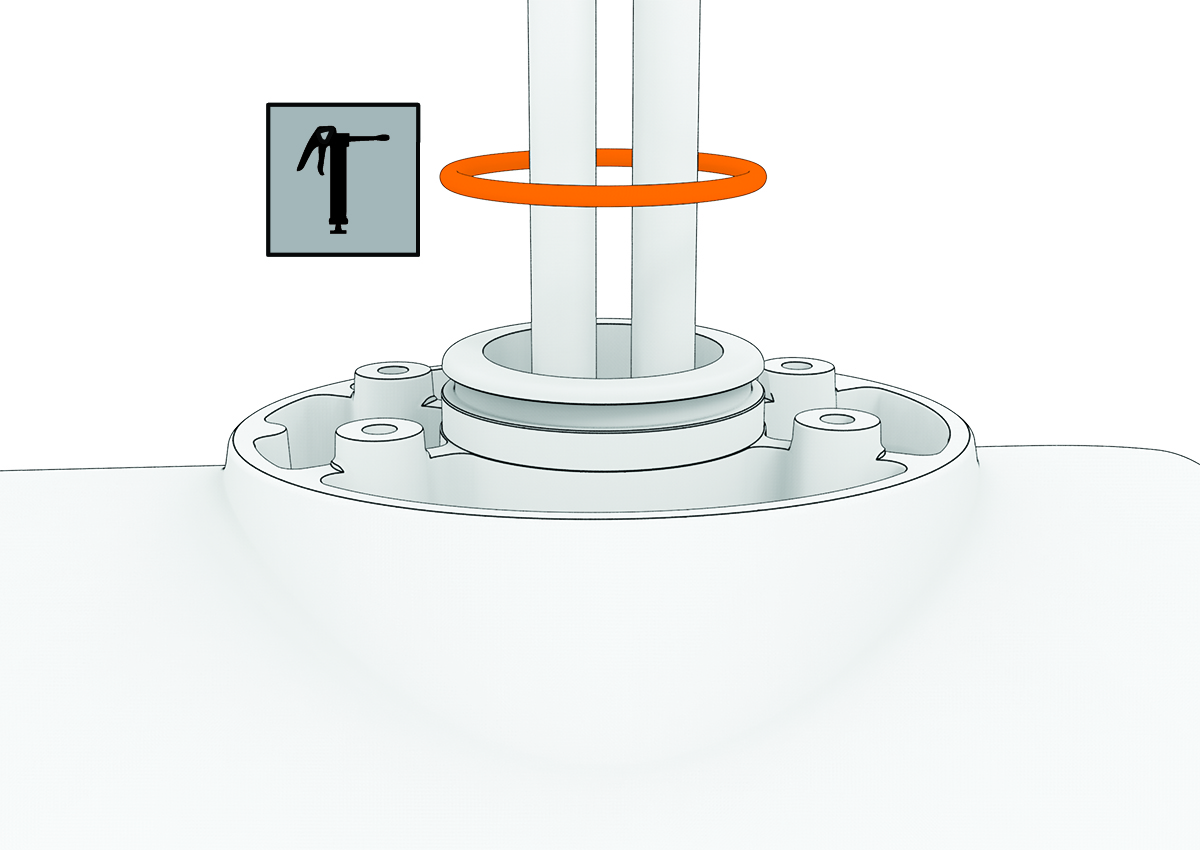
Remove the 36 mm (17/16 in.) O-ring from the top of the propeller drive motor, and discard it.
-
Thread the cables from the propeller drive motor through the new 36 mm (17/16 in.) O-ring in the shaft and motor hardware service kit.
-
Using the packet included in the shaft and motor hardware service kit, apply grease to the new 36 mm (17/16 in.) O-ring.
-
Place the new 36 mm (17/16 in.) O-ring in the groove on the top of the propeller drive motor.
-
If the power and data cables from the propeller drive motor are not already aligned and bundled, straighten, align, and bundle them with tape.
If the power and data cables are not straight and aligned, they may not feed through the shaft smoothly.
-
Feed the power and data cables from the propeller drive motor up through the shaft until they emerge from the top.
NOTICE
When the cables emerge into the shaft cap, you must avoid pulling on connectors. The connectors on the propeller drive motor cables are fragile and may be damaged by pulling. If necessary, pull only on the cables themselves and avoid putting any strain on the connectors.
-
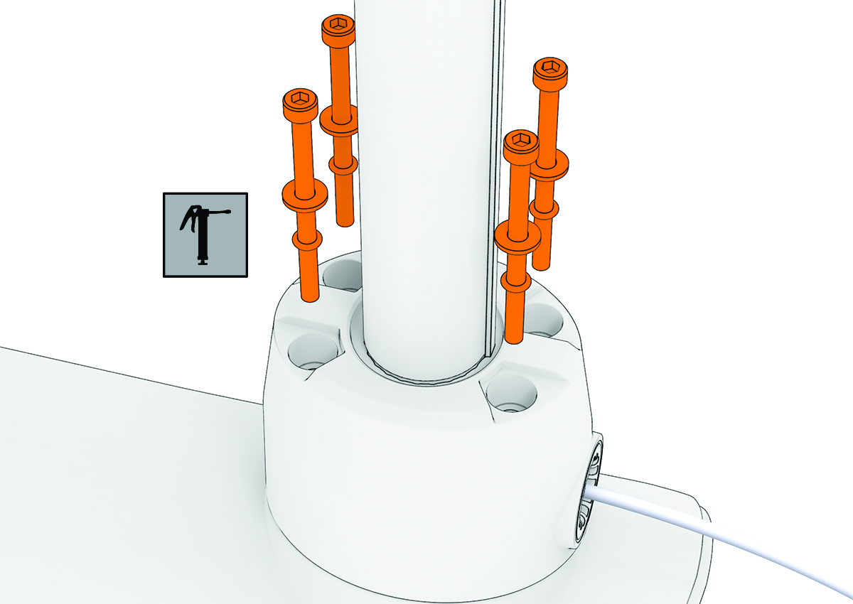
Prepare the four bolts in the shaft and motor hardware service kit by placing a washer and a 4.75 mm (3/16 in.) O-ring on each one.
-
Using the grease packet included in the shaft and motor hardware service kit, apply grease to the 4.75 mm (3/16 in.) O-ring on each bolt.
Avoid getting grease on the bolt threads.
Remember:
If you did not previously apply thread-locking compound in the four mounting holes for these bolts, you must apply it before installing these bolts.
-
Using a ball-head 4 mm hex bit or wrench, thread all four of the prepared bolts approximately halfway to make sure that the shaft base and the propeller drive motor are properly aligned.
-
With the shaft base and the propeller drive motor properly aligned, lightly tighten all four bolts by hand.
-
Using a torque wrench, tighten all four bolts to 4 N-m (35 lbf-in).