Connecting to Power Through an Ignition Switch
This method of connection is used most often on ski boats, wake boats, and similar sport or recreational vessels where power to the engines is toggled often. For these installations, a quick standby and faster startup time is desired so that music can be stopped and begin playing again as quickly as possible after restarting the engines. When in standby mode, the stereo uses up to 350 mA, and you should connect the power wires through a circuit breaker or manual switch to avoid draining the battery when you are not using the boat.
When you are not using the vessel for an extended period of time, you should remove power to the stereo using the circuit breaker or other manual switch on the yellow wire to avoid draining the battery.
-
Consult this diagram to plan the wire connections.
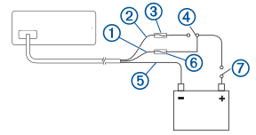
Item
Description
Notes
Yellow wire
You must connect this wire to the same power source as the ignition or ACC switch.
Red wire
You must connect this wire to the ignition or ACC switch before you connect it to the same power source as the yellow wire.
1 A fuse (not included)
You must install this fuse on the red wire before you connect the red wire to the ignition or ACC switch.
Ignition or ACC switch
Connecting the red wire to this switch allows the stereo to enter a low-power standby mode when you turn off the engines, so it can start up faster when you turn on the engines again.
Black wire
Ground (-)
Appropriately-rated inline fuse or circuit breaker (Important Power Connection Information for New Installations)
An appropriately-rated fuse or circuit breaker is required and must be rated for the current requirements of the stereo installation and the power cable used. The fuse or circuit breaker must be located at the battery end of the supply cable.
Appropriately-rated circuit breaker for a power-distribution cable (Important Power Connection Information for New Installations)
If the stereo is connected to a power-distribution cable or bus that also supplies other equipment, this should include a fuse or circuit breaker rated for the power-distribution cable used. This fuse or circuit breaker must be located within 150 mm (6 in.) of the battery.
When you turn on the ignition switch, the stereo turns on along with other accessory electronics. When you turn off the ignition switch, the stereo enters a low-power standby mode.