Removing the Release Latch
-
With the motor in the stowed position, use a 4 mm hex bit or wrench to remove the two hex head screws
 from the latch spring cover
  .
.
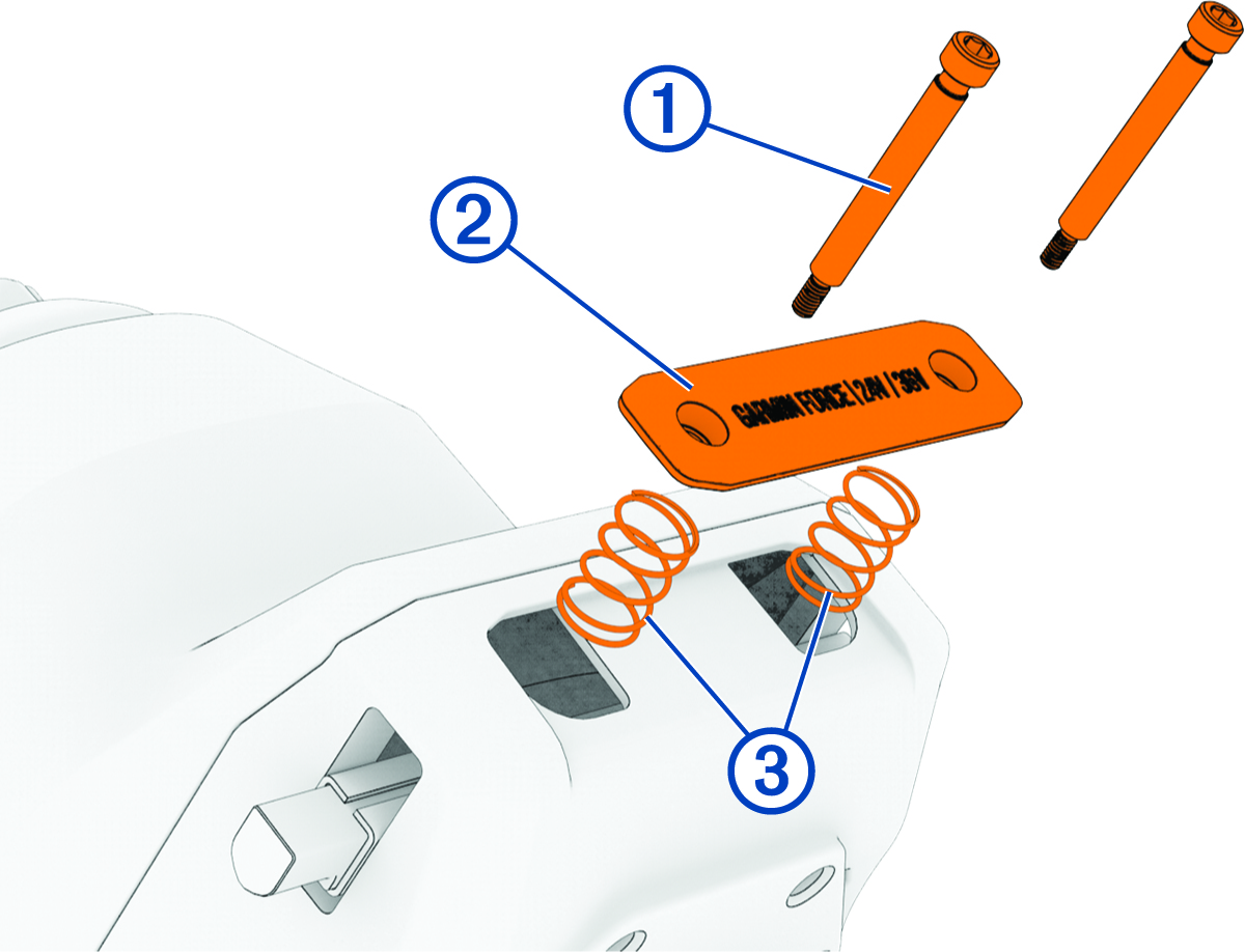
NOTE: The latch spring cover is under spring tension. Take care that you do not lose the cover and springs during disassembly.
-
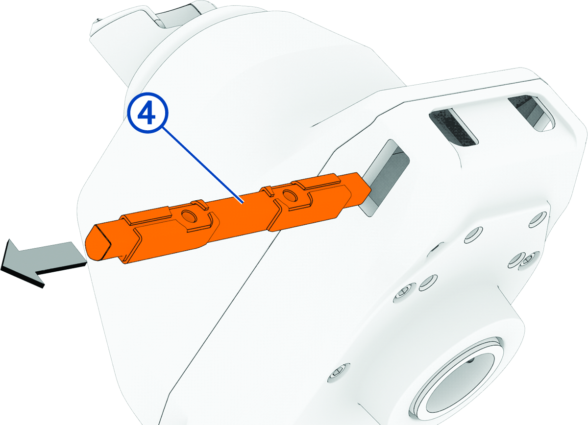
Slide the release latch
 out of the steering servo housing.