Installation
Mounting Considerations
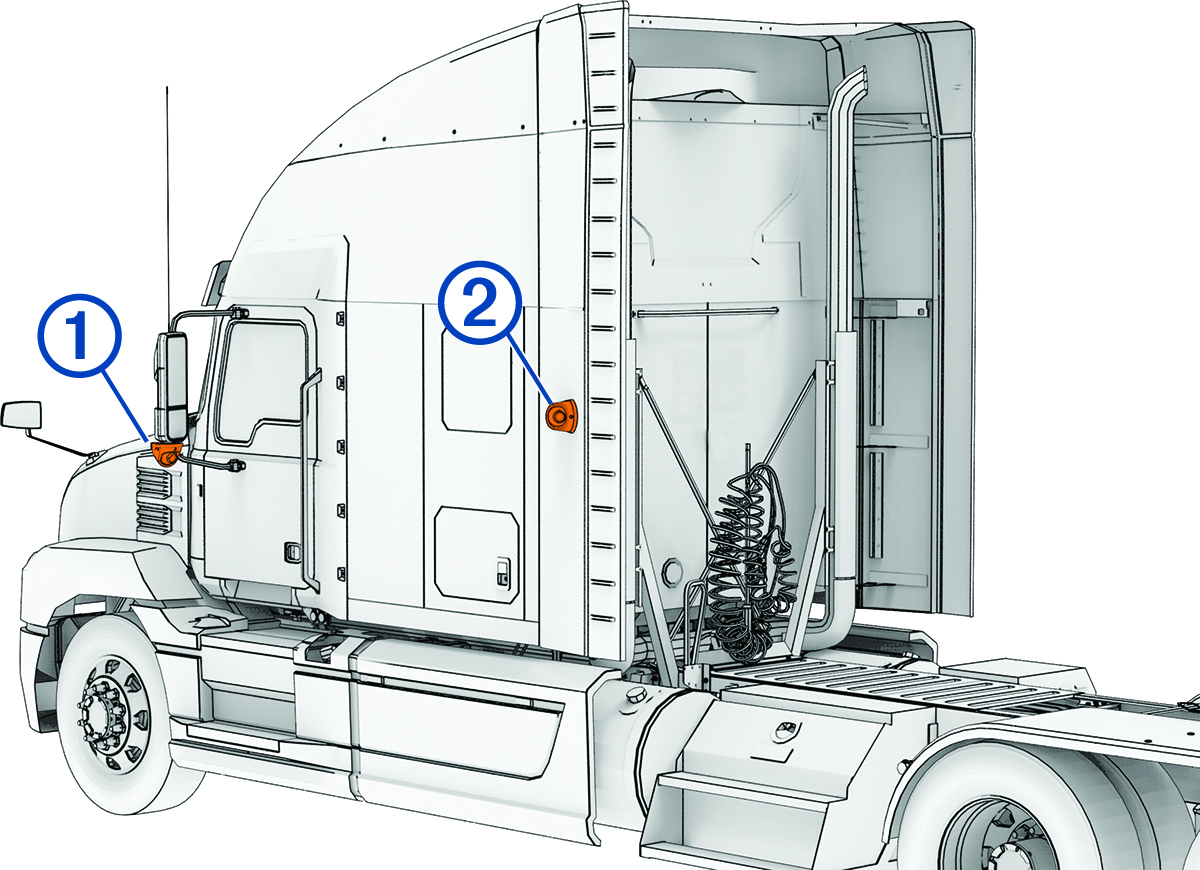
When selecting locations to mount the cameras and transmitter box, observe these considerations.
-
You can mount the cameras to the side mirrors or to any stable, flat surface with a good view of the side of your vehicle or trailer.
-
You should mount the cameras at a height of at least 120 cm (4 ft.) and no more than 240 cm (8 ft.) from the road surface.
-
You should mount the cameras in locations that provide sufficient clearance to route cables and use installation tools.
-
You should test a mounting location before you permanently mount the cameras.
-
You should ensure the transmitter box is placed within 3 m (10 ft.) of your phone, tablet, or navigator.
-
You should mount the transmitter box securely to a rigid surface inside of your vehicle that allows access to the memory card.
-
You should ensure the transmitter box is placed within reach of the camera cables. Make sure to consider cable routing and cable management to ensure you have sufficient cable before permanently mounting the transmitter box.
-
The transmitter box gets hot during extended use. You should mount the transmitter box to an unupholstered surface with good airflow.
-
When routing cables, protect them from sharp objects. You should use rubber grommets (not included) when routing cables through metal panels to protect the cables.
Testing the Camera and Transmitter Locations
You should test the camera and transmitter locations to plan a permanent installation.
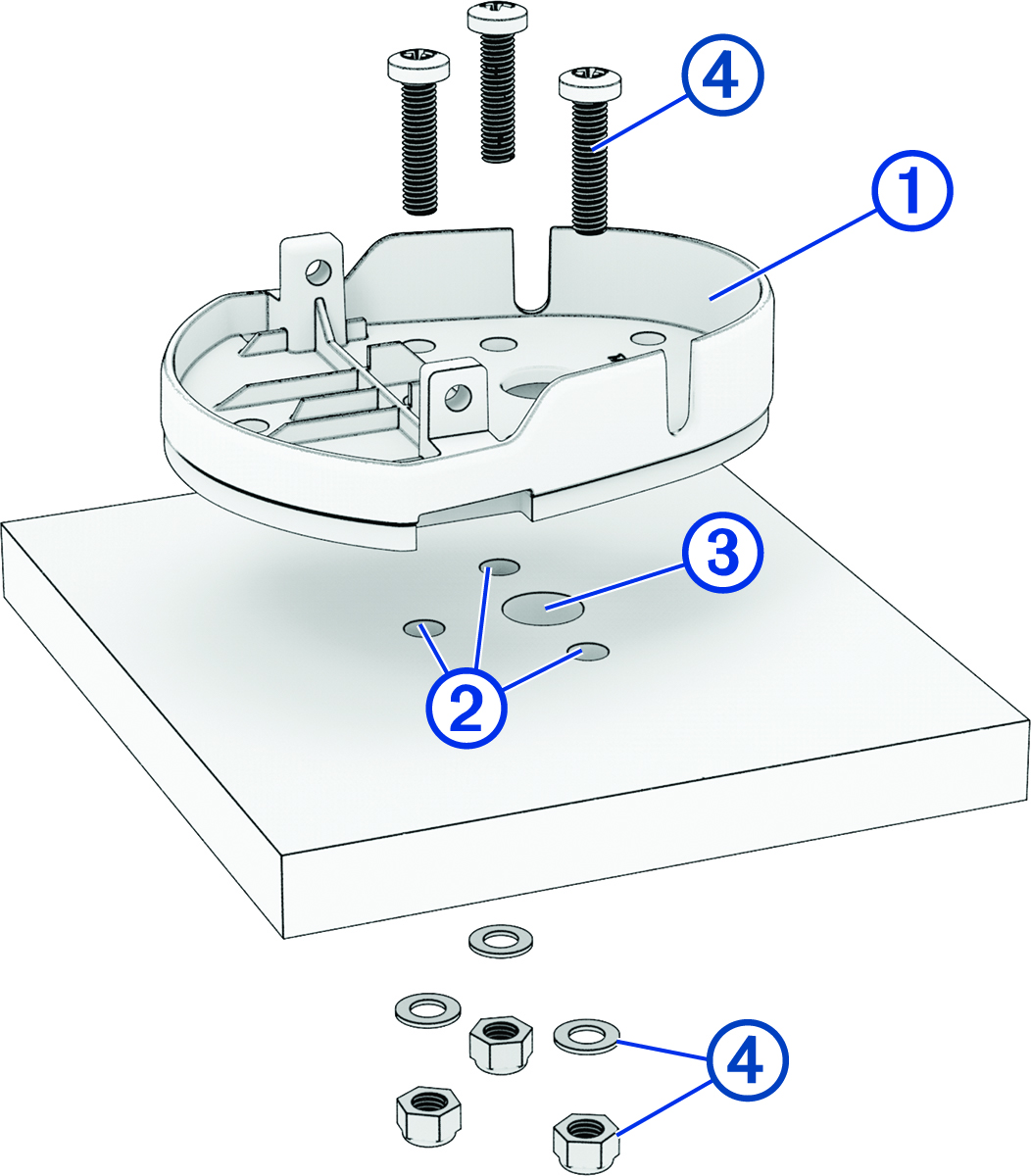
Mounting the Camera Screw-Down Base Plate
Before you can mount the camera screw-down base plate using the included hardware, you must select a mounting location where you can access both sides of the mounting surface.
-
Using the camera screw-down base
plate as a mounting template, mark the mounting surface with the three screw
locations .
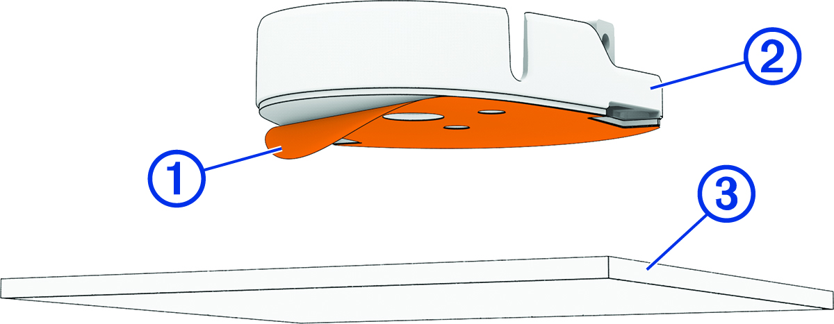
Mounting the Camera Adhesive Base Plate
The adhesive base plate is intended for a long-term installation and can be difficult to remove. You should carefully consider the mounting location before you install the base plate.
For the best results, the ambient temperature should be from 21° to 38°C (from 70° to 100°F) while installing the adhesive base plate on your vehicle. The adhesive may not bond correctly if the temperature is outside of this range. If you need to install the base plate at lower temperatures, you must clear all snow, ice, and moisture from the mounting surface and warm the surface before installing the base plate.
Before you install the adhesive base plate onto your vehicle, you should review the mounting considerations.
-
After you have selected a mounting location with a clear view, remove the protective film from the bottom of the base plate .
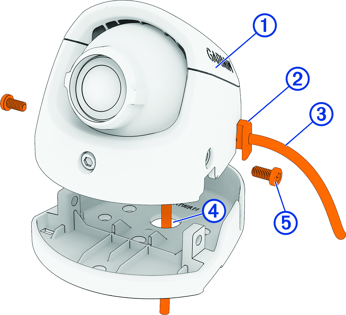
Securing the Camera to the Base Plate
Depending on your installation, you can route the camera cable either through the base plate and the mounting surface, or through the slot in the side of the camera.
-
Hold the camera over the base plate.
Connecting the Camera Cables
Only use the heat gun to apply heat to the heat-shrink tubing in a well-ventilated area. Do not use the heat gun near clothing or bare skin. Doing so can result in property damage or serious injury.
You must apply heat shrink tubing to the camera cable connection point to protect the cameras from electrostatic discharge and/or an electrical short circuit. Failure to install heat shrink tubing could result in damage to the cameras or poor product performance.
-
Connect the coaxial cable from each camera to the coaxial cables on the transmitter box.
TIP: The cables are not labeled for the left or right sides. You can set which camera is on the left or right side using the Garmin Drive app.
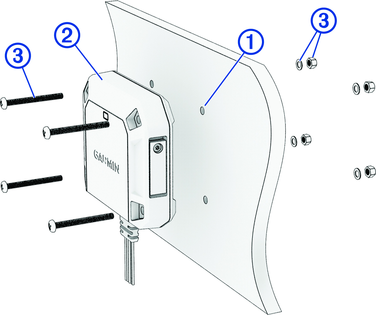
Mounting the Transmitter Box
Before you can mount the transmitter box using the included hardware, you must select a rigid mounting surface inside your vehicle where you can access both sides of the mounting surface.
-
Mark the pilot holes using the included mounting template.
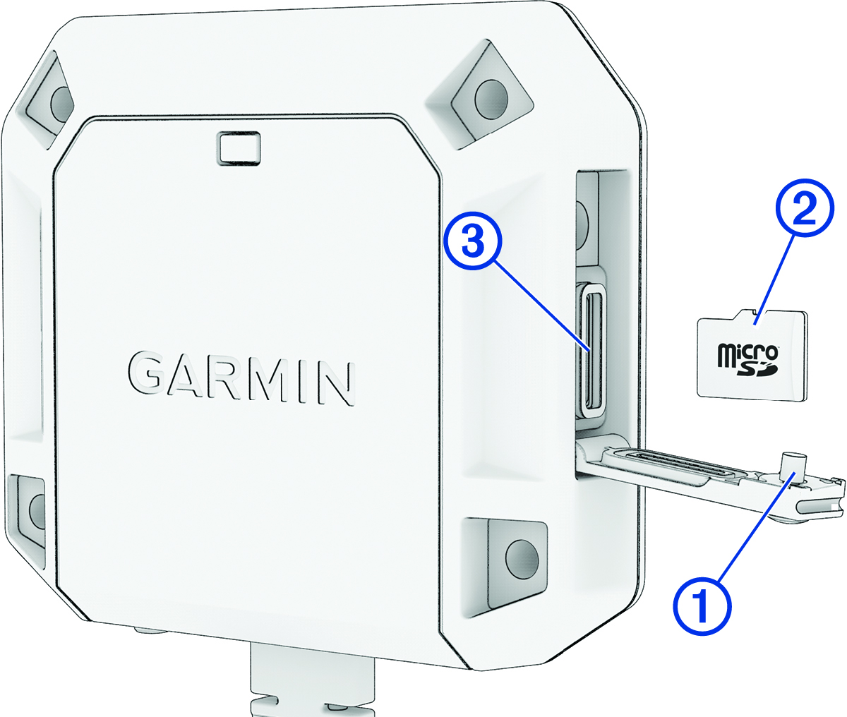
Installing a Memory Card in the Transmitter Box
To record video, you must install a compatible memory card (not included). You can use microSDHC or microSDXC memory cards from 16 to 512 GB with a speed rating of class 10 or faster. Memory cards must be formatted with the exFAT file system.
-
Using the included star drive screwdriver, loosen the screw securing the weathercap door to the transmitter box.
Connecting the Turn Signal Wires
You can connect the turn signal wires from the transmitter box to the left and right turn signals in your vehicle. The dēzl™ DualView system includes tap splice connectors to help you connect to your turn signals without needing to cut and splice the wires manually. You can set the wires for the left or right sides using the Garmin Drive app.
For most installations, you can connect to the positive wires on the turn signal lights located on the sides of your vehicle. Contact your vehicle manufacturer for specific questions related to turn signal connections in your vehicle.
Power Connection
When connecting the device to power, you must connect the red and black wires to the power source.
- Red wire
-
-
This wire provides power to the device.
-
If it is necessary to extend this wire, use wire that is at least 22 AWG (0.34 mm2).
-
If your installation requires a fuse, you can connect the included fuse to this wire (In-line Fuse Cable). The fuse should be installed as close to the power source as possible.
-
- Black wire
-
-
This is the ground wire, and you must connect it to the negative terminal of the power source or to a common ground.
-
If it is necessary to extend this wire, use wire that is at least 22 AWG (0.34 mm2).
-
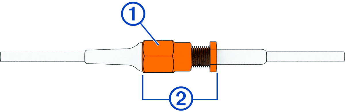
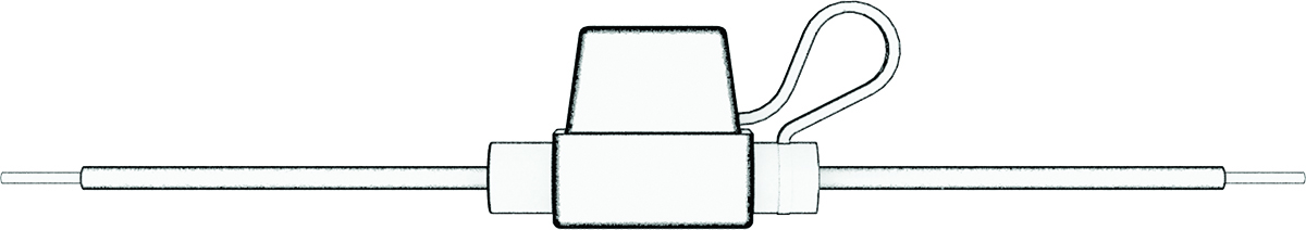
In-line Fuse Cable
Garmin® strongly recommends having an experienced installer with the proper knowledge of electrical systems install the in-line fuse cable. Incorrectly wiring the power cable or the in-line fuse cable can result in damage to the vehicle or the battery and can cause bodily injury.
In many cases, you must install the included in-line fuse cable on the device power cable to protect the device from excessive electrical current.
-
You must install the included in-line fuse cable if you are connecting the power cable directly to the vehicle battery.
-
If you are connecting the power cable to an accessory power source or bus bar that already has a suitable fuse or a protective circuit, installing the included in-line fuse is not necessary.
-
When installing the in-line fuse cable, you should connect it to the red system power wire using the included splice connector.
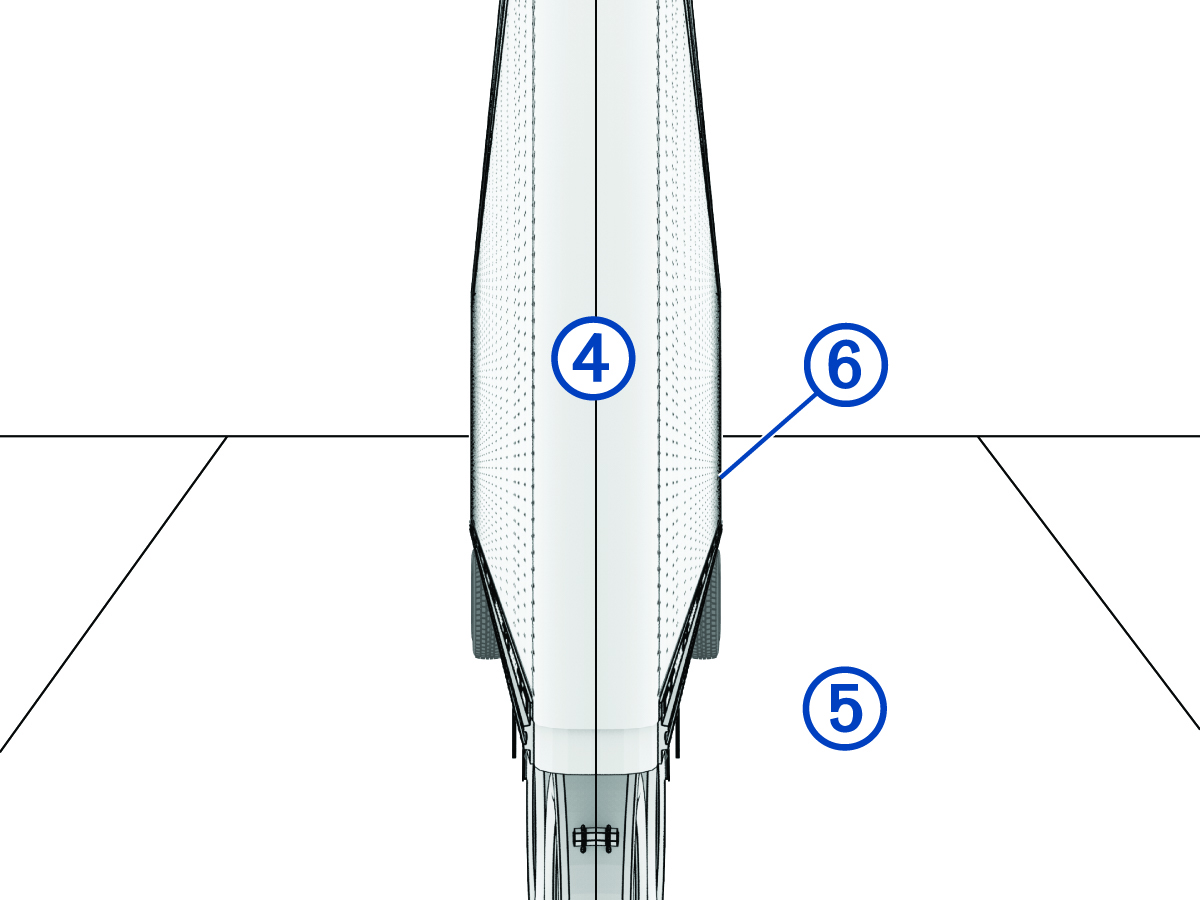
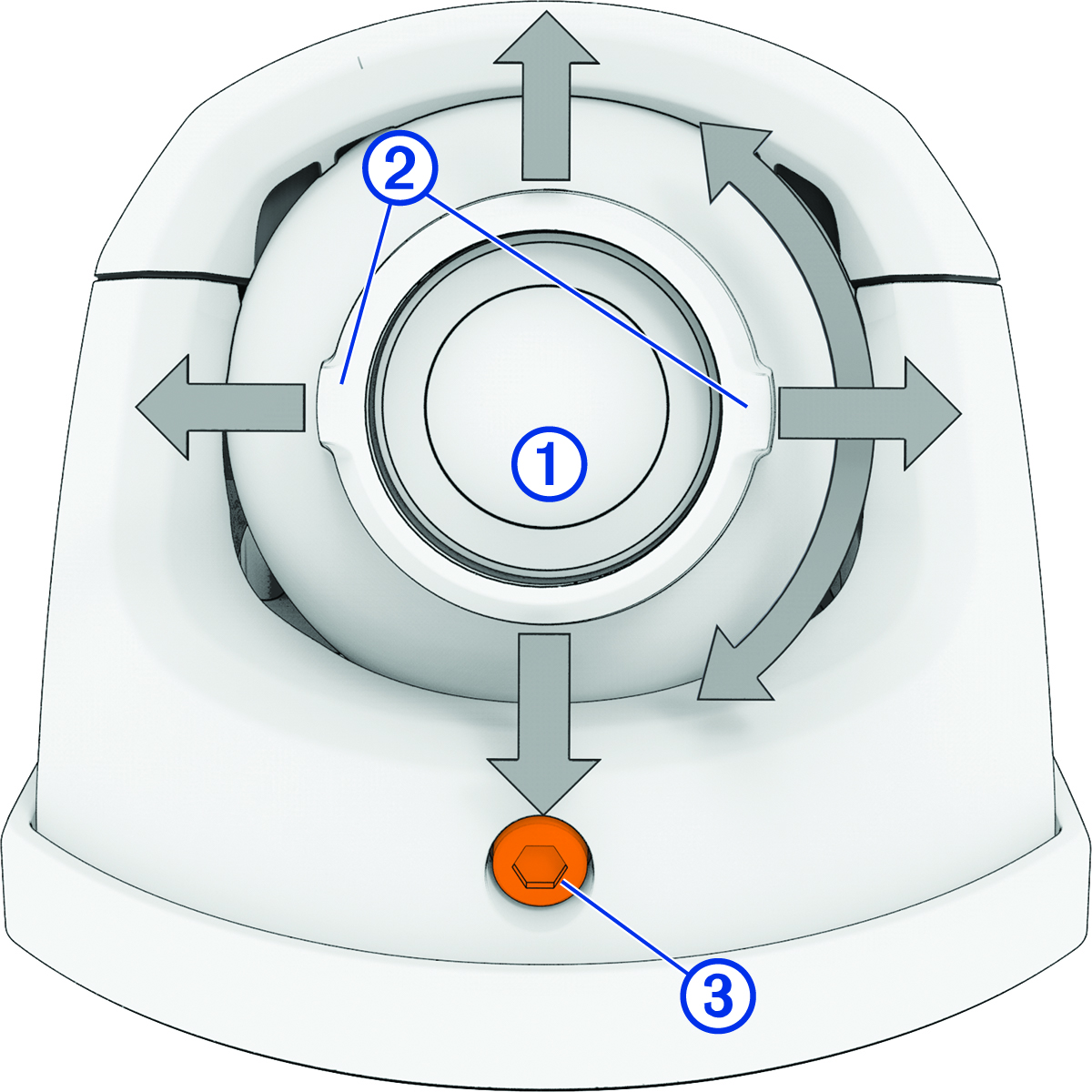
Adjusting the Camera Lens
The cameras use an adjustable lens module inside an enclosure mounted to a base plate. The adjustable lens module can tilt up to 45 degrees and roll clockwise or counterclockwise up to 180 degrees. The markings at the edges of the lens indicate the horizon line. After you have verified the field of view on your connected screen, you must lock the camera into its configuration by tightening the locking screw using the included hex wrench.
-
During initial setup in the
Garmin Drive app, verify that both sides of your vehicle appear in the center of the video feed.