Routing the Power and Transducer Cables Through the Mount
Label identifying the parts bag required for this procedure:

To avoid damaging the power and transducer cables when deploying and stowing the trolling motor and to avoid interference with the GPS and heading sensors in the motor, you must route the cables through the right (starboard) side of the mount and secure them using the included hardware. You must not route the power cable through the left (port) side of the mount, and it is not possible to install the included brackets on the left (port) side. The left (port) side is reserved for additional accessories or transducer cables that you may install in the future.
-
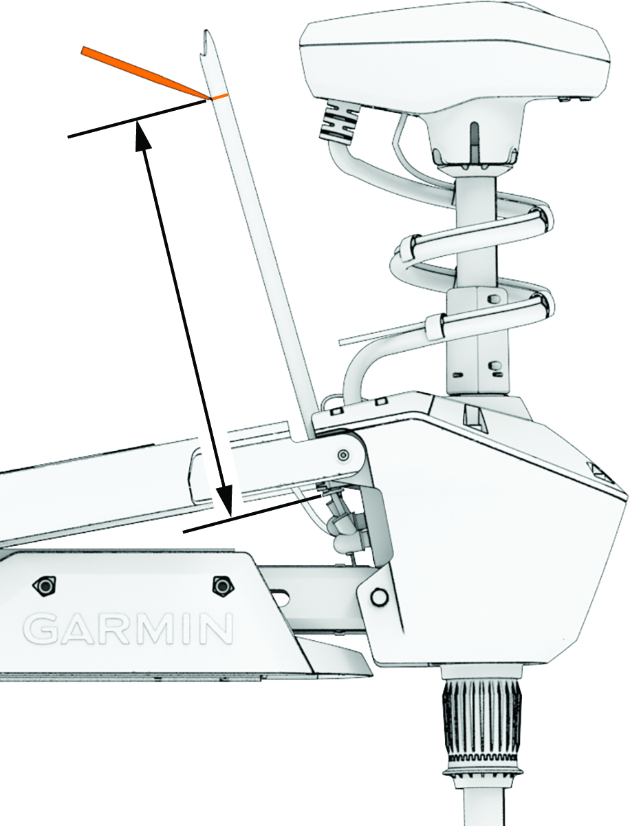
Measure approximately 40 cm (16 in.) on the power cable from where it connects to the steering servo housing, and look for the mark on the cable applied at the factory.
-
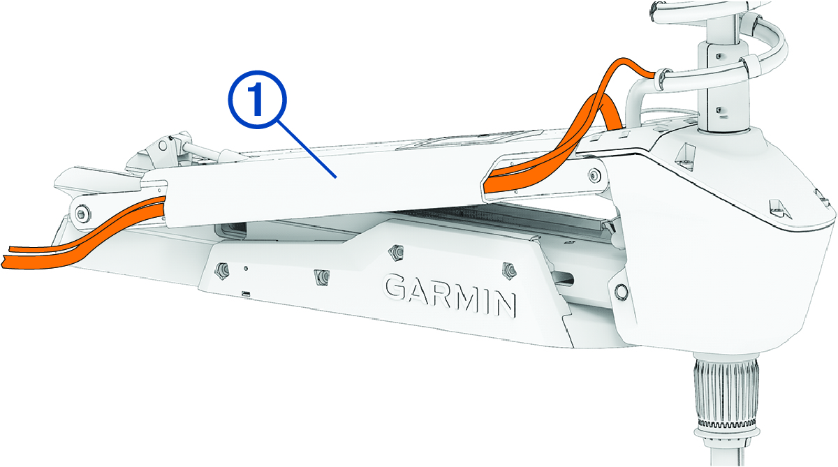
With the motor in the deployed position, route the transducer cable through the channel along the right (starboard) side of the mount
 .
.
TIP: To determine the right (starboard) side of the mount, stand in a location where you can read the information on the display panel. -
Leaving a rounded bend in the cables
 , hold them against the side of the mount where they enter the channel.
-
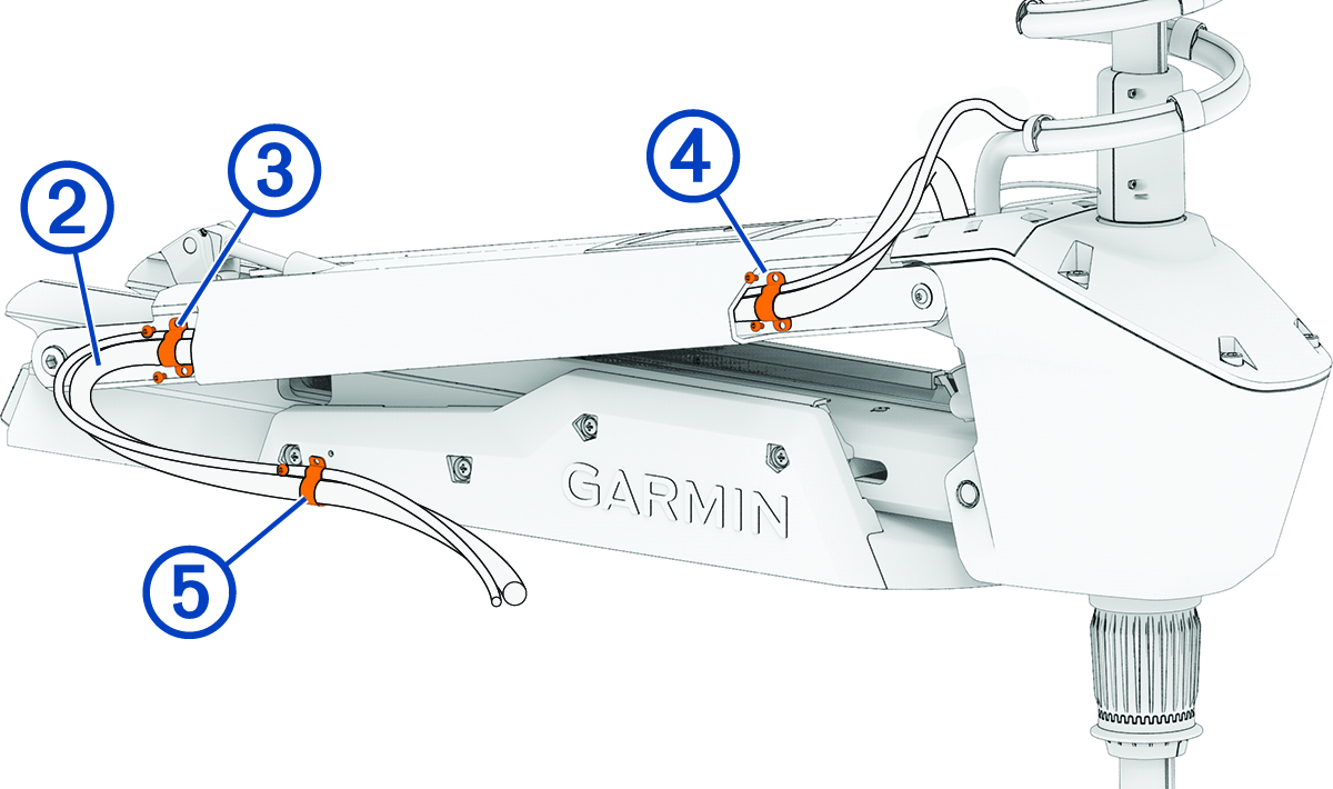
At the marked location on the power cable, place one of the brackets
 that have two screw holes over the cables and against the mount, aligning the holes on the bracket with the holes on the mount.
-
Place the other bracket
 that has two screw holes over the cables and against the mount, aligning the holes on the bracket with the holes on the mount.
-
Insert the lower tab on the remaining bracket into a slot below the cables
 , and rotate the bracket toward the mount base to hold the cables.