Connection Considerations
When connecting this device to power and to other Garmin® devices, you should observe these considerations.
-
The power and ground connections to the battery must be checked to make sure they are secured and cannot become loose.
-
The cables may be packaged without the locking rings installed. The cables should be routed before the locking rings are installed.
-
After installing a locking ring on a cable, you should make sure the ring is securely connected and the o-ring is in place so the power or data connection remains secure.
Connector View
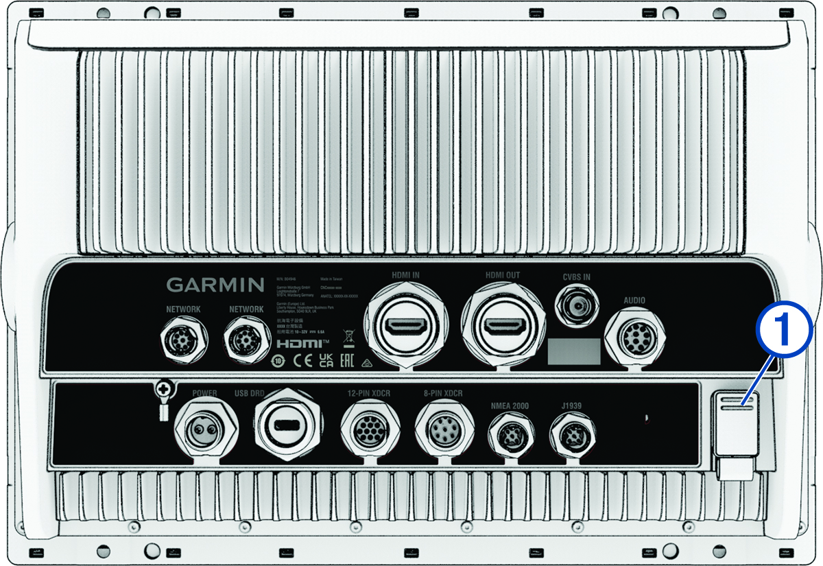
The connectors and locations are the same across all of the GPSMAP® 9000xsv series models. A GPSMAP 9x13xsv model is shown below.
|
|
Two internal card readers. Each supports up to a 1 TB microSD® memory card, formatted to exFAT with speed class 10 or higher. |
|---|---|
|
POWER |
Power |
|
NETWORK |
Garmin BlueNet™ network ports (Garmin BlueNet Network Considerations) |
|
HDMI IN |
HDMI® input compatible with HDMI devices up to 4K at 60 fps |
|
HDMI OUT |
HDMI out |
|
USB DRD |
Dual-Role-Data (DRD) USB-C® that can be configured as either a host or a client. |
|
AUDIO |
NMEA® 0183 and audio out |
|
CVBS IN |
Composite video in |
|
NMEA 2000 |
NMEA 2000® network |
|
8-PIN XDCR |
8-pin transducer |
|
12-PIN XDCR |
12-pin transducer |
|
J1939 |
J1939 network |
Connecting to Power
When connecting the power cable, do not remove the inline fuse holder. To prevent the possibility of personal injury or product damage caused by fire or overheating, the appropriate fuse must be in place as indicated in the product specifications. Connecting the power cable without the appropriate fuse in place voids the product warranty.
You should connect the red wire to the power source through the ignition or another manual switch to turn the device on and off.
Additional Grounding Consideration

This device should not need additional chassis grounding in most installation situations. If you experience interference, you can use the grounding screw on the housing to connect the device to the water ground of the boat to help avoid the interference.
Power Cable Extensions

|
|
Splice |
|---|---|
|
|
|
|
|
Fuse (10 A) |
|
|
20.3 cm (8 in.) |
|
|
Battery |
|
|
20.3 cm (8 in.) |
|
|
11 m (36 ft.) maximum extension |
Station Connection Considerations
-
Devices earlier than the GPSMAP 8000 series and GPSMAP 8500 series cannot be used in a station.
-
Although it is not necessary, it is recommended that you install all of the devices you plan to use in one station near each other.
-
All of the devices you plan to use in stations must be connected to the Garmin BlueNet network (Garmin BlueNet Network Considerations). No additional, special connections are necessary.
-
Stations are created and modified using the device software. See the device owner's manual for more information.
Garmin BlueNet Network Considerations
This device can connect to additional Garmin devices to share data such as radar, sonar, and detailed mapping using Garmin BlueNet technology. For more information about Garmin BlueNet technology, including best practices for properly constructing a network that contains both Garmin BlueNet devices and legacy Garmin Marine Network devices, go to garmin.com/manuals/bluenet.
When connecting Garmin BlueNet devices and legacy Garmin Marine Network devices to this device, observe these considerations.
-
The NETWORK ports on the device each act as a Garmin BlueNet network switch. Any Garmin BlueNet device can connect to any NETWORK port to share data with all devices on the boat connected by a Garmin BlueNet cable.
-
You can connect legacy Garmin Marine Network devices to this device if you install a Garmin BlueNet 30 gateway.
-
All devices connected to the Garmin BlueNet network must be connected to the same ground. If multiple power sources are used for Garmin BlueNet network devices, you must tie all ground connections from all power supplies together using a low resistance connection or tie them to a common ground bus bar, if available.
-
You must use a Garmin BlueNet network cable for all Garmin BlueNet network connections.
-
You must not use third-party CAT5 cable and RJ45 connectors for Garmin BlueNet network connections.
-
Additional Garmin BlueNet cables and connectors are available from your Garmin dealer or from garmin.com.
-
NMEA 2000 Considerations
If you are connecting to an existing NMEA 2000 network, identify the NMEA 2000 power cable. Only one NMEA 2000 power cable is required for the NMEA 2000 network to operate properly.
A NMEA 2000 Power Isolator (010-11580-00) should be used in installations where the existing NMEA 2000 network manufacturer is unknown.
If you are installing a NMEA 2000 power cable, you must connect it to the boat ignition switch or through another in-line switch. NMEA 2000 devices will drain your battery if the NMEA 2000 power cable is connected to the battery directly.
This device can connect to a NMEA 2000 network on your boat to share data from NMEA 2000 compatible devices such as a GPS antenna or a VHF radio. The included NMEA 2000 cables and connectors allow you to connect the device to your existing NMEA 2000 network. If you do not have an existing NMEA 2000 network you can create a basic one using cables from Garmin.
This device is not powered through the NMEA 2000 network. You must connect the device to a power source (Connecting to Power).
If you are unfamiliar with NMEA 2000, you should read the Technical Reference for NMEA 2000 Products at garmin.com/manuals/nmea_2000.
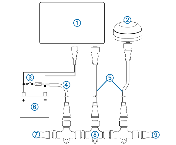
The port labeled NMEA 2000 is used to connect the device to a standard NMEA 2000 network.
|
Item |
Description |
|---|---|
|
|
NMEA 2000 compatible Garmin device |
|
|
GPS antenna |
|
|
Ignition or in-line switch |
|
|
NMEA 2000 power cable |
|
|
NMEA 2000 drop cable |
|
|
12 Vdc power source |
|
|
NMEA 2000 terminator or backbone cable |
|
|
NMEA 2000 T-connector |
|
|
NMEA 2000 terminator or backbone cable |
NMEA 0183 Connection Considerations
-
The chartplotter provides one Tx (transmit) port and one Rx (receive) port.
-
Each port has 2 wires, labeled A and B according to the NMEA 0183 convention. The corresponding A and B wires of each internal port should be connected to the A (+) and B (-) wires of the NMEA 0183 device.
-
You can connect one NMEA 0183 device to the Rx port to input data to this chartplotter, and you can connect up to three NMEA 0183 devices in parallel to the Tx port to receive data output by this chartplotter.
-
See the NMEA 0183 device installation instructions to identify the transmit (Tx) and receive (Rx) wires.
-
You must use 28 AWG (0.08 mm²), shielded, twisted-pair wiring for extended runs of wire. Solder all connections and seal them with heat-shrink tubing.
-
Unless instructed for specific installation types, you should not connect the NMEA 0183 data wires from this device to power ground.
-
The power cable from the chartplotter and the NMEA 0183 devices must be connected to a common power ground.
-
The internal NMEA 0183 ports and communication protocols are configured on the chartplotter. See the NMEA 0183 section of the chartplotter owner's manual for more information.
-
See the chartplotter owner's manual for a list of the approved NMEA 0183 sentences that the chartplotter supports.
NMEA 0183 with Audio Cable Pinout
The optional NMEA 0183 with audio cable (010-12852-00) includes bare wires and an RCA connector for an audio out connection to a stereo, including Fusion® stereos. This cable can be purchased from garmin.com or your local Garmin dealer.
You can connect the RCA connector to the AUX input of the stereo. Audio received from the HDMI input to the chartplotter is output to the stereo.
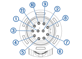
The NMEA 0183 with audio cable provides one differential NMEA 0183 input and output port.
|
Pin |
Wire Function |
Wire Color |
|---|---|---|
|
|
NMEA 0183 Rx/A (In +) |
White/orange |
|
|
NMEA 0183 Rx/B (In -) |
White |
|
|
NMEA 0183 Tx/B (Out -) |
Pink |
|
|
NMEA 0183 Tx/A (Out +) |
Gray |
|
|
Ground |
Black |
|
|
Alarm |
Yellow |
|
|
Accessory on |
Orange |
|
|
Ground (shield) |
Brown |
|
|
Audio Left Channel |
White |
|
|
Audio Common |
Blue/red |
|
|
Audio Right Channel |
Red |
NMEA 0183 Device Connections
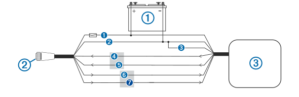
This diagram illustrates two-way connections for both sending and receiving data. You can also use this diagram for one-way communication. To receive information from a NMEA 0183 device, refer to items , , , , and when connecting the Garmin device. To transmit information to a NMEA 0183 device, refer to items , , , , and when connecting the Garmin device.
|
Item |
Description |
|---|---|
|
|
Power source |
|
|
Power/NMEA 0183 cable |
|
|
NMEA 0183 device |
|
Item |
Garmin Wire Function |
Garmin Wire Color |
NMEA 0183 Device Wire Function |
|---|---|---|---|
|
|
Power |
Red |
Power |
|
|
Power ground |
Black |
Power ground |
|
|
Data ground |
Black |
Data ground |
|
|
Rx/A (In +) |
Brown |
Tx/A (Out +) |
|
|
Rx/B (In -) |
Violet |
Tx/B (Out -) |
|
|
Tx/A (Out +) |
Blue |
Rx/A (In +) |
|
|
Tx/B (Out -) |
Gray |
Rx/B (In -) |
If the NMEA 0183 device has only one input (receive, Rx) wire (no A, B, +, or -), you must leave the gray wire unconnected.
If the NMEA 0183 device has only one output (transmit, Tx) wire (no A, B, +, or -), you must connect the violet wire to ground.
Lamp or Horn Connections
The device can be used with a lamp, a horn, or both, to sound or flash an alert when the chartplotter displays a message. This is optional, and the alarm wire is not necessary for the device to function normally. When connecting the device to a lamp or horn, observe these considerations.
-
The alarm circuit switches to a low-voltage state when the alarm sounds.
-
The maximum current is 100 mA, and a relay is needed to limit the current from the chartplotter to 100 mA.
-
To toggle visual and audible alerts manually, you can install single-pole, single-throw switches.

|
Item |
Description |
|---|---|
|
|
Power source |
|
|
Power cable |
|
|
Horn |
|
|
Lamp |
|
|
NMEA 0183 cable |
|
|
Relay (100 mA coil current) |
|
|
Toggle switches to enable and disable lamp or horn alerts |
|
Item |
Wire Color |
Wire Function |
|---|---|---|
|
|
Red |
Power |
|
|
Black |
Ground |
|
|
Yellow |
Alarm |
J1939 Engine Network Connection Considerations
You must use a Garmin GPSMAP J1939 accessory cable when connecting the chartplotter to the J1939 engine network to prevent corrosion due to moisture. Using a different cable voids your warranty.
If you have an existing engine network on your boat, it should already be connected to power. Do not add any additional power supply.
This chartplotter can connect to an engine network on your boat to read data from compatible devices such as certain engines. The engine network follows a standard and uses proprietary messages.
You should consult the manufacturer of your engine or engine network when connecting the chartplotter. Some manufacturers may have requirements you must follow when connecting to avoid unexpected behavior.
The port labeled J1939 is used to connect the device to the existing engine network. You must route the cable within 6 m (20 ft.) of the engine network backbone.
The Garmin GPSMAP J1939 accessory cable requires connection to a power source and proper termination. For more information on connecting to your engine network, see the manufacturer's engine documentation.
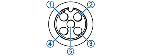
|
Pin |
Wire Color |
Description |
|---|---|---|
|
|
Bare |
Shield |
|
|
Red |
Power, positive |
|
|
Black |
Power, negative |
|
|
White |
CAN High |
|
|
Blue |
CAN Low |
HDMI Video Considerations
To prevent corrosion due to moisture, you must use Garmin GPSMAP accessory cables when connecting the chartplotter to the video source or display. Do not connect a media player stick directly into the back of the chartplotter. Using different cables or connecting a media player stick into the back of the chartplotter voids your warranty.
This chartplotter allows video input from HDMI video sources, such as a Chromecast™ device or a Blu-Ray™ player. You can view protected HDMI content (HDCP content) on the chartplotter screen, but are limited with how you can view that content on additional devices.
Through the HDMI OUT port, you can display the chartplotter on an external screen, such as a television or monitor. You can view HDCP content on an external monitor that supports industry HDCP standards.
HDMI video is shared across the Garmin BlueNet network and across the Garmin Marine Network, but it is not shared across the NMEA 2000 network. HDCP content cannot be shared across the Garmin network to GPSMAP 8000 series or older chartplotters. HDCP content can be shared by a GPSMAP 9000 series chartplotter only to other GPSMAP 9000 series chartplotters connected to the Garmin BlueNet network.
The Garmin GPSMAP HDMI accessory cable is 4.5 m (15 ft) long. If you need a longer cable, you should use an active HDMI cable only. You need an HDMI coupler to connect the two HDMI cables.
You can use an adapter cable to power a media player stick using a USB port on the chartplotter. The USB DRD port can supply up to 2.5 W to power a media player stick. The USB port can supply up to 4.5 W to power a media player stick
You must make all cable connections in a dry environment.
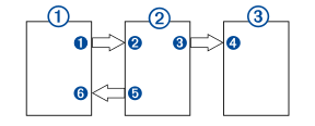
Devices
|
Item |
Device |
|---|---|
|
|
HDMI source, such as a Chromecast device |
|
|
GPSMAP chartplotter |
|
|
Monitor, such as a computer or television |
Connections
|
From |
To |
Cable |
|---|---|---|
|
HDMI source's HDMI OUT port |
Chartplotter's HDMI IN port |
Garmin HDMI Cable |
|
Chartplotter's HDMI OUT port |
Monitor's HDMI IN port |
Garmin HDMI Cable |
|
Chartplotter's USB DRD port |
HDMI source's USB port |
Adapter cable to power the HDMI source, if possible. The USB DRD port supplies a maximum output of 2.5 W. |
Composite Video Considerations
This chartplotter allows video input from composite video sources using the port labeled CVBS IN. When connecting composite video, you should observe these considerations.
-
The CVBS IN port uses a BNC connector. You can use a BNC to RCA adapter to connect a composite-video source with RCA connectors to the CVBS IN port.
-
Video is shared across the Garmin Marine Network, but it is not shared across the NMEA 2000 network.
Touchscreen Controls for a Connected Computer
To prevent corrosion due to moisture, you must use Garmin GPSMAP accessory cables when connecting the chartplotter to the computer. Using different cables voids your warranty.
You can connect the chartplotter to a computer to see the computer screen on the chartplotter touchscreen and control the computer using the chartplotter touchscreen. To see the computer screen, you must connect the computer to the HDMI IN port. To control the computer, you must connect the computer to the USB DRD port.
The Garmin HDMI accessory cable (010-12390-20) is 4.5 m (15 ft) long. If you need a longer cable, you should use an active HDMI cable only. You need an HDMI coupler to connect the two HDMI cables.
To avoid potential communication errors, you should use the correct USB cable for your chartplotter. You should not use an adapter to change the USB connector type on an older cable.
You must make all cable connections in a dry environment.
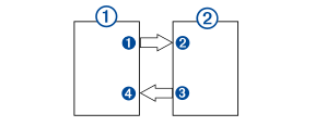
Devices
|
Item |
Device |
|---|---|
|
|
Computer |
|
|
GPSMAP chartplotter |
Connections
|
From |
To |
Cable |
|---|---|---|
|
Computer's HDMI OUT port |
Chartplotter's HDMI IN port |
Garmin HDMI Cable (010-12390-20) |
|
Chartplotter's USB DRD port |
Computer's USB port |
Garmin USB-C to USB-A Cable (010-12390-14) |