Mounting Considerations
This device should be mounted in a location that is not exposed to extreme temperatures or conditions. The temperature range for this device is listed in the product specifications. Extended exposure to temperatures exceeding the specified temperature range, in storage or operating conditions, may cause device failure. Extreme-temperature-induced damage and related consequences are not covered by the warranty.
Using the included hardware and template, you can flush mount the chartplotter in the dashboard.
When selecting a mounting location, observe these considerations.
-
You should mount the chartplotter to provide an optimal viewing angle as you operate your boat.
-
You must select a location that is strong enough to support the weight of the chartplotter and protect it from excessive vibration or shock.
-
You should select a location that allows for easy access to all interfaces, such as the keypad, touchscreen, and card reader, if applicable.
-
To avoid interference with a magnetic compass, you must not mount the chartplotter closer to a compass than the compass-safe distance value listed in the product specifications.
-
You must select a location that allows room for the routing and connection of all cables.
-
If the mounting location is in direct sunlight and in a horizontal orientation, ensure that the installation location meets as many of the following criteria as possible:
-
Sufficient air flow
-
Proper ventilation
-
Cooling source on the front and rear of the chartplotter
-
Method to shade the display using a canopy, window tint, or shroud
NOTE: If possible, you should meet all of these criteria when installing the chartplotter. -
Bail Mounting the Device
If you are mounting the bracket on fiberglass with screws, it is recommended to use a countersink bit to drill a clearance counterbore through only the top gel-coat layer. This will help to avoid cracking in the gel-coat layer when the screws are tightened.
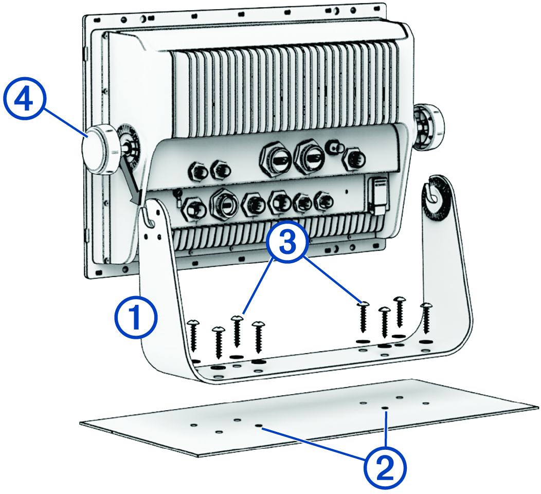
You can use the bracket to bail mount the device on a flat surface.
-
Using the bail-mount bracket as a template, mark the pilot holes .
Flush Mounting the Device
Be careful when cutting the hole to flush mount the device. There is only a small amount of clearance between the case and the mounting holes, and cutting the hole too large could compromise the stability of the device after it is mounted.
Use only the included hardware when mounting this device. Using mounting hardware not provided with the device may damage the device.
To avoid potential damage to the powder coating, use only the included screws to mount the device. Using screws other than the ones included will void your warranty.
Do not remove the blue, rubber protective bumper until after the installation is complete. The bumper helps protect the device from damage during installation.
If you will not have access to be back of the device and the microSD® memory card slots after installations, you should install the microSD memory card prior to installation.
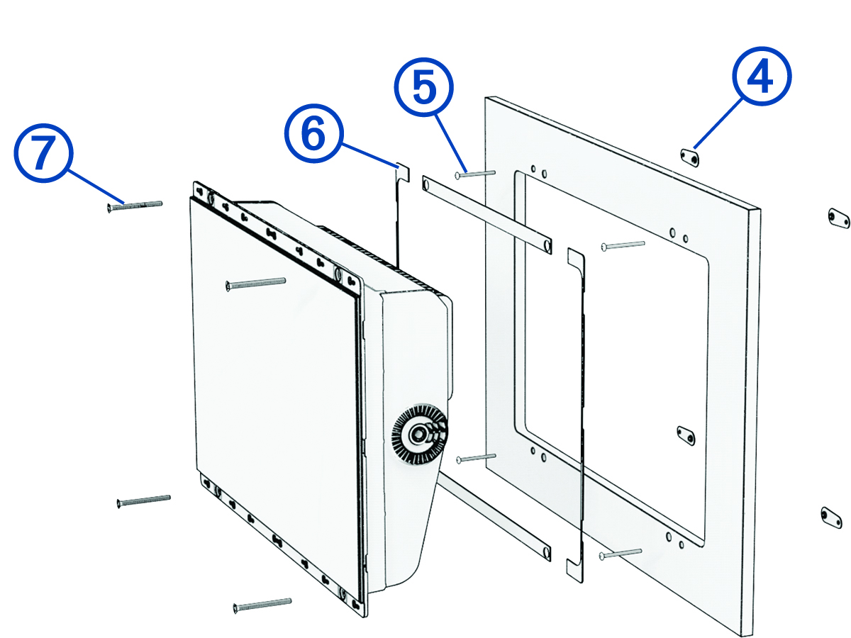
The included template and hardware can be used to flush mount the device in your dashboard. There are three options for hardware based on the mounting surface material.
-
You can drill pilot holes and use the included wood screws.
-
You can drill holes and use the included nut plates and machine screws. The nut plates can add stability to a thinner surface.
-
You can drill holes, tap them to M4, and use the included machine screws.
-
If using the nut plates, starting in one corner of the template, place a nut plate over the larger hole drilled in step 9.
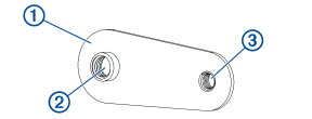
The smaller hole on the nut plate should line up with the smaller 3.6 mm (9/64 in.) hole on the template.
-
Starting in one corner of the mounting location, place a nut plate on the back of the mounting surface, lining up the large and small holes.
The raised portion of the nut plate should fit into the larger hole.