Mounting Location and Water Resistance
When mounting the speaker in an area exposed to weather or water, you must mount the speaker on a vertical surface. If you mount the speaker on a horizontal surface facing up, water can gather in and around the speaker, causing damage over time.
If you intend to mount the speakers outside the boat, you must mount them in a location well above the waterline, where they are not submerged or damaged by docks, pilings, or other pieces of equipment. When mounted correctly, these speakers are rated for protection from the front of the speaker. Water exposure and damage to the rear of the speaker voids the warranty. This includes situations when the speakers are mounted in a sealed enclosure, especially if they are exposed to wash down. Using an enclosure with a port or vent exposed to the outside environment may allow water to collect and damage the speaker.
You must turn off the audio system before making any connections to the source unit, amplifier, or speakers. Failure to do so could result in permanent damage to the audio system.
You should protect all terminals and connections from grounding and from each other. Failure to do so could result in permanent damage to the audio system and void the product warranty.
The mounting method and materials used can vary depending on the vessel application.
When mounting the speakers, observe these considerations.
-
You must select a mounting location that protects the rear of the speaker from moisture exposure.
-
You must select a mounting location that has sufficient clearance for the mounting depth of the speakers as specified in the product specifications.
-
You should select a flat, vertical mounting surface for the best seal.
-
You must select a mounting location where the panel thickness is not thinner or thicker than specified in the product specifications.
-
You should protect the speaker wires from sharp objects, and always use grommets when wiring through panels.
-
To avoid interference with a magnetic compass, you should not mount the speakers closer to a compass than the compass-safe distance value listed in the product specifications.
Selecting the correct mounting location optimizes the performance of each speaker. The speakers are designed to perform in the widest possible range of mounting locations, but the more you plan the installation, the better the speakers' sound will be.
Mounting the Speaker
-
Using a #2 Phillips screwdriver, turn the screws to extend the mounting tabs to lightly hold the speaker to mounting surface.
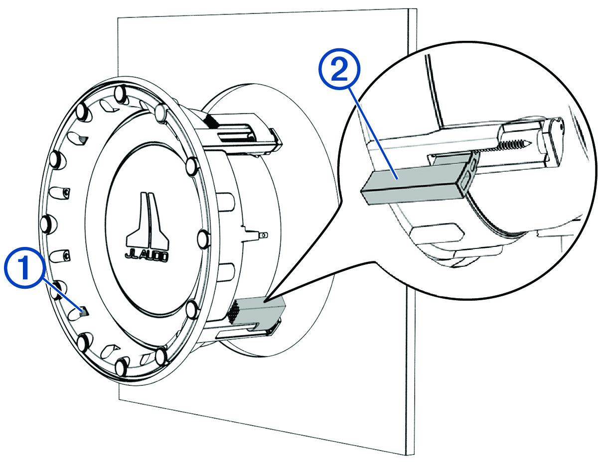

Although you may use a power screwdriver to initially turn the screws on the mounting tabs, you must use a torque screwdriver to complete the installation. Using power tools to fully tighten the screws could result in permanent damage to the speaker and void the product warranty.
Speaker Wire Gauge Guide
Do not use copper-clad aluminum (CCA) wire for this installation. CCA wire is more prone to breaking and its use could also result in poor product performance.
|
Distance between the amplifier and speaker |
Wire gauge |
|---|---|
|
From 0 to 28 ft. (from 0 to 8.5 m) |
16 AWG (1.3 through 1.5 mm2) |
|
From 28 to 69 ft. (from 8.5 to 21 m) |
12 AWG (3 through 4 mm2) |
|
Distance between the amplifier and speaker |
Wire gauge |
|---|---|
|
From 0 to 14 ft. (from 0 to 4 m) |
16 AWG (1.3 through 1.5 mm2) |
|
From 14 to 35 ft. (from 4 to 10.5 m) |
12 AWG (3 through 4 mm2) |